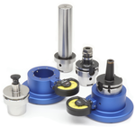
Without a dimensionally correct tool holder taper, it is not possible to ensure a proper spindle/tool holder connection.
Using tool holder dimensional gauges, the taper and other key features can be checked for wear, or new holders can be checked as a part of incoming inspection. In addition, gauges are a necessity when manufacturing tool holders. Units are available for CAT/DIN/BT tapers in basic contact gauges, dial indicator gauges, as well as air gauges. For HSK, we offer dial indicator, electronic, and air gauges.
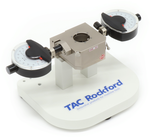
HSK Tool Holder Inspection Gauge

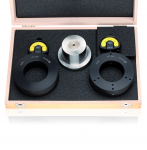
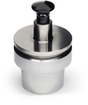
HSK Inspection Gauge Masters

High Precision Gauge Masters

30° Clamping Angle
30° Clamping Angle (978 Series)
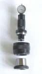
Dial Indicator (410 Series)

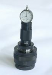
Dial Indicator (968 Series)
Electronic

Drive Key
Pneumatic
Without a dimensionally correct tool holder taper, it is not possible to ensure a proper spindle/tool holder connection.
Using tool holder dimensional gauges, the taper and other key features can be checked for wear, or new holders can be checked as a part of incoming inspection. In addition, gauges are a necessity when manufacturing tool holders. Units are available for CAT/DIN/BT tapers in basic contact gauges, dial indicator gauges, as well as air gauges. For HSK, we offer dial indicator, electronic, and air gauges.
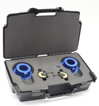
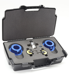
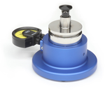

Designed to detect tool holder taper wear in seconds.
Maintain machining accuracy and extend spindle life with our high-precision Taper Inspection Gauge. Designed for the machine shop floor, this system allows operators to identify critical taper wear and deformation before it leads to scrapped parts or costly spindle damage.
Rapid Diagnostics: Verify tool holder integrity in seconds with a simple, repeatable process.
High Resolution: Compatible with 8mm stem indicators. Indicators not included: resolutions of 0.001mm, 0.0005mm, or 0.00005″ available from TAC Rockford.
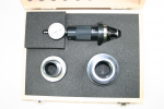
Portable: Includes two heavy-duty Fixture Bases and a custom-fitted carrying case to keep your precision instruments protected in industrial environments.
Flexible Calibration: While the 410.148 Certified Taper Master is recommended, the system is designed to work with a “known good” tool holder for quick shop-floor referencing.
Additional product information can be found on the Details tab below.
| HSK Taper | HSK-B/D/F | Part Number | ||||||
|---|---|---|---|---|---|---|---|---|
| HSK-A/C/E 25 + HSK-B/D/F 32 | 410.124.125.000 | |||||||
| HSK-A/C/E 32 + HSK-B/D/F 40 | 410.124.132.000 | |||||||
| HSK-A/C/E 40 + HSK-B/D/F 50 | 410.124.140.000 | |||||||
| HSK-A/C/E 50 | 410.124.150.000 | |||||||
| HSK-A/C/E 63 | 410.124.163.000 | |||||||
| HSK-B/D/F 63 | 410.124.663.000 | |||||||
| HSK-A/C/E 80 + HSK-B/D/F 100 | 410.124.180.000 | |||||||
| HSK-B/D/F 80 | 410.124.680.000 | |||||||
| HSK-A/C 100 + HSK-B/D/F 125 | 410.124.190.000 | |||||||
| HSK-A 125 + HSK-B/D/F 160 | 410.124.192.000 | |||||||
| HSK-A 160 | 410.124.196.000 |
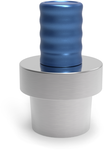
These taper master gauges can be used for zeroing the dial indicators on our HSK Tool Holder Inspection Gauges.
| HSK Taper | Part Number | |||||||
|---|---|---|---|---|---|---|---|---|
| HSK-A/C/E 25 + HSK-B/D/F 32 | 410.148.125.000 | |||||||
| HSK-A/C/E 32 + HSK-B/D/F 40 | 410.148.132.000 | |||||||
| HSK-A/C/E 40 + HSK-B/D/F 50 | 410.148.140.000 | |||||||
| HSK-A/C/E 50 | 410.148.150.000 | |||||||
| HSK-A/C/E 63 | 410.148.163.000 | |||||||
| HSK-B/D/F 63 | 410.148.663.000 | |||||||
| HSK-A/C 80 | 410.148.180.000 | |||||||
| HSK-B/D/F 80 | 410.148.680.000 | |||||||
| HSK-A/C 100 | 410.148.190.000 |
| HSK-A/C/E Taper | HSK-B/D/F Taper | Part Number | ||||||
|---|---|---|---|---|---|---|---|---|
| HSK-A/C/E 25 | HSK-B/D/F 32 | 410.145.125.000 | ||||||
| HSK-A/C/E 32 | HSK-B/D/F 40 | 410.145.132.000 | ||||||
| HSK-A/C/E 40 | HSK-B/D/F 50 | 410.145.140.000 | ||||||
| HSK-A/C/E 50 | HSK-B/D/F 63 | 410.145.150.000 | ||||||
| HSK-A/C/E 63 | HSK-B/D/F 80 | 410.145.163.000 | ||||||
| HSK-A/C/E 80 | HSK-B/D/F 100 | 410.145.180.000 | ||||||
| HSK-A/C/E 100 | HSK-B/D/F 125 | 410.145.190.000 |

")
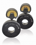
HSK 63 Tool Holder Inspection Gauge Master
These taper master gauges can be used for zeroing the dial indicators on our HSK Tool Holder Inspection Gauges.
| HSK Taper | Part Number | |||||||
|---|---|---|---|---|---|---|---|---|
| HSK-A/C/E 25 + HSK-B/D/F 32 | 410.148.125.000 | |||||||
| HSK-A/C/E 32 + HSK-B/D/F 40 | 410.148.132.000 | |||||||
| HSK-A/C/E 40 + HSK-B/D/F 50 | 410.148.140.000 | |||||||
| HSK-A/C/E 50 | 410.148.150.000 | |||||||
| HSK-A/C/E 63 | 410.148.163.000 | |||||||
| HSK-B/D/F 63 | 410.148.663.000 | |||||||
| HSK-A/C 80 | 410.148.180.000 | |||||||
| HSK-B/D/F 80 | 410.148.680.000 | |||||||
| HSK-A/C 100 | 410.148.190.000 |

")
High Precision HSK Gauge Master
To check the extremely small tolerances required by the DIN and ISO standards for HSK tool holders.
| HSK-A/C/E Taper | HSK-B/D/F Taper | Part Number | ||||||
|---|---|---|---|---|---|---|---|---|
| HSK-A/C/E 25 | HSK-B/D/F 32 | 410.145.125.000 | ||||||
| HSK-A/C/E 32 | HSK-B/D/F 40 | 410.145.132.000 | ||||||
| HSK-A/C/E 40 | HSK-B/D/F 50 | 410.145.140.000 | ||||||
| HSK-A/C/E 50 | HSK-B/D/F 63 | 410.145.150.000 | ||||||
| HSK-A/C/E 63 | HSK-B/D/F 80 | 410.145.163.000 | ||||||
| HSK-A/C/E 80 | HSK-B/D/F 100 | 410.145.180.000 | ||||||
| HSK-A/C/E 100 | HSK-B/D/F 125 | 410.145.190.000 |
")
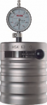
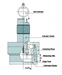
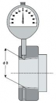
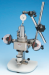
Using the calibrated master, the distance of the 30 degree clamping slope relative to l 2 is preset using the dial indicator holder. The tool taper to be measured is placed in the centering piece, allowing the variation of the taper to be measured.
| HSK A/C/E | HSK B/D/F | l 6 / JS 10 | d 6 | Part Number | ||||
|---|---|---|---|---|---|---|---|---|
| HSK-A 25 | HSK 32 | 7.21 | 15 | 410.230.125.000 | ||||
| HSK-A 32 | HSK 40 | 8.92 | 19 | 410.230.132.000 | ||||
| HSK-A 40 | HSK 50 | 11.42 | 23 | 410.230.140.000 | ||||
| HSK-A 50 | HSK 63 | 14.13 | 29 | 410.230.150.000 | ||||
| HSK-A 63 | HSK 80 | 18.13 | 37 | 410.230.163.000 | ||||
| HSK-A 80 | HSK 100 | 22.85 | 46 | 410.230.180.000 | ||||
| HSK-A 100 | HSK 125 | 28.56 | 58 | 410.230.190.000 | ||||
| HSK-A 125 | HSK 160 | 36.27 | 73 | 410.230.192.000 | ||||
| HSK-A 160 | – | 45.98 | 92 | 410.230.196.000 |

")
To ensure sustained accuracy at HSK interfaces, we recommend comparison measuring of the geometry of HSK tool shanks and spindles at regular intervals. These checks should become more frequent with an increased change rate at the interface.
| Taper | l1 | d1 | Part Number | |||||
|---|---|---|---|---|---|---|---|---|
| HSK-A/C/E 25 | 7.21 | 15 | 410.231.125.000 | |||||
| HSK-A/C/E 32 | 8.92 | 19 | 410.231.132.000 | |||||
| HSK-A/C/E 40 | 11.42 | 23 | 410.231.140.000 | |||||
| HSK 50 | 14.13 | 29 | 410.231.150.000 | |||||
| HSK-A/C/E 63 | 18.13 | 37 | 410.231.163.000 | |||||
| HSK-A/C/E 80 | 22.85 | 46 | 410.231.180.000 | |||||
| HSK-A/C/E 100 | 28.56 | 58 | 410.231.190.000 |

")
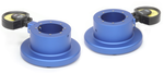
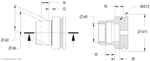
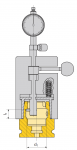
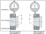
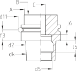
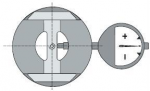
Both measuring gauges are set to zero with the calibrated taper plug gauge. When an HSK tool holder is inserted in the ring gauges, deviations in diameters d2 or d3 are shown on the indicator.
| HSK A/C/E | HSK B/D/F | d2 | d3 | Part Number | ||||
|---|---|---|---|---|---|---|---|---|
| HSK-A 25 | HSK 32 | 19 | 18.15 | 410.210.125.000 | ||||
| HSK-A 32 | HSK 40 | 24 | 23.27 | 410.210.132.000 | ||||
| HSK-A 40 | HSK 50 | 30 | 29.05 | 410.210.140.000 | ||||
| HSK-A 50 | HSK 63 | 38 | 36.90 | 410.210.150.000 | ||||
| HSK-A 63 | HSK 80 | 48 | 46.53 | 410.210.163.000 | ||||
| HSK-A 80 | HSK 100 | 60 | 58.10 | 410.210.180.000 | ||||
| HSK-A 100 | HSK 125 | 75 | 72.60 | 410.210.190.000 | ||||
| HSK-A 125 | HSK 160 | 95 | 91.95 | 410.210.192.000 | ||||
| HSK-A 160 | – | 120 | 116.00 | 410.210.196.000 |
")
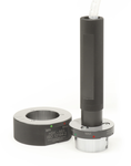
HSK Tool Holder Taper Gauge
| Taper | Diameter | Part Number | ||||||
|---|---|---|---|---|---|---|---|---|
| HSK-A/C/E 25 | 19 | 410.211.125.000 | ||||||
| HSK-A/C/E 32 | 24 | 410.211.132.000 | ||||||
| HSK-A/C/E 40 | 30 | 410.211.140.000 | ||||||
| HSK-A/C/E 50 | 38 | 410.211.150.000 | ||||||
| HSK-A/C/E 63 | 48 | 410.211.163.000 | ||||||
| HSK-A/C/E 80 | 60 | 410.211.180.000 | ||||||
| HSK-A/C/E 100 | 75 | 410.211.190.000 |

")
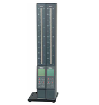
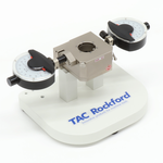
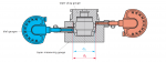
The four transducers mounted in the measuring ring are used for differential measurement of gauge dimensions d2 and d3. Deviations from the calibrated taper plug gauge are shown on the two indicator columns.
| HSK A/C/E | HSK B/D/F | d2 | d3 | l2 | l3 | Part Number | ||
|---|---|---|---|---|---|---|---|---|
| Indicator Column | 410.220.000.000 | |||||||
| HSK-A 25 | HSK 32 | 19.000 | 18.1500 | 2.5 | 8.5 | 410.220.125.000 | ||
| HSK-A 32 | HSK 40 | 24.007 | 23.2755 | 3.2 | 7.3 | 410.220.132.000 | ||
| HSK-A 40 | HSK 50 | 30.007 | 29.0551 | 4.0 | 4.5 | 410.220.140.000 | ||
| HSK-A 50 | HSK 63 | 38.009 | 36.9068 | 5.0 | 11.0 | 410.220.150.000 | ||
| HSK-A 63 | HSK 80 | 48.010 | 46.5370 | 6.3 | 14.7 | 410.220.163.000 | ||
| HSK-A 80 | HSK 100 | 60.012 | 58.1082 | 8.0 | 19.0 | 410.220.180.000 | ||
| HSK-A 100 | HSK 125 | 75.013 | 72.6082 | 10.0 | 24.0 | 410.220.190.000 |

")
Available for HSK 32, 40, 50, 63, 80, 100, 125, 160
| Taper | Part Number | |||||||
|---|---|---|---|---|---|---|---|---|
| HSK-A/C 32 | 410.240.132.000 | |||||||
| HSK-A/C 40 | 410.240.140.000 | |||||||
| HSK-A/C 50 | 410.240.150.000 | |||||||
| HSK-A/C 63 | 410.240.163.000 | |||||||
| HSK-A/C 80 | 410.240.180.000 | |||||||
| HSK-A/C 100 | 410.240.190.000 | |||||||
| HSK-A/C 125 | 410.240.192.000 | |||||||
| HSK-A/C 160 | 410.240.196.000 |

")
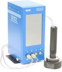
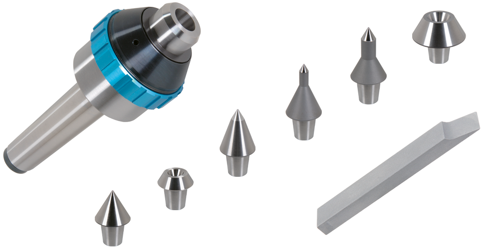
Pneumatic HSK Tool Holder Taper Gauge
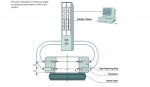
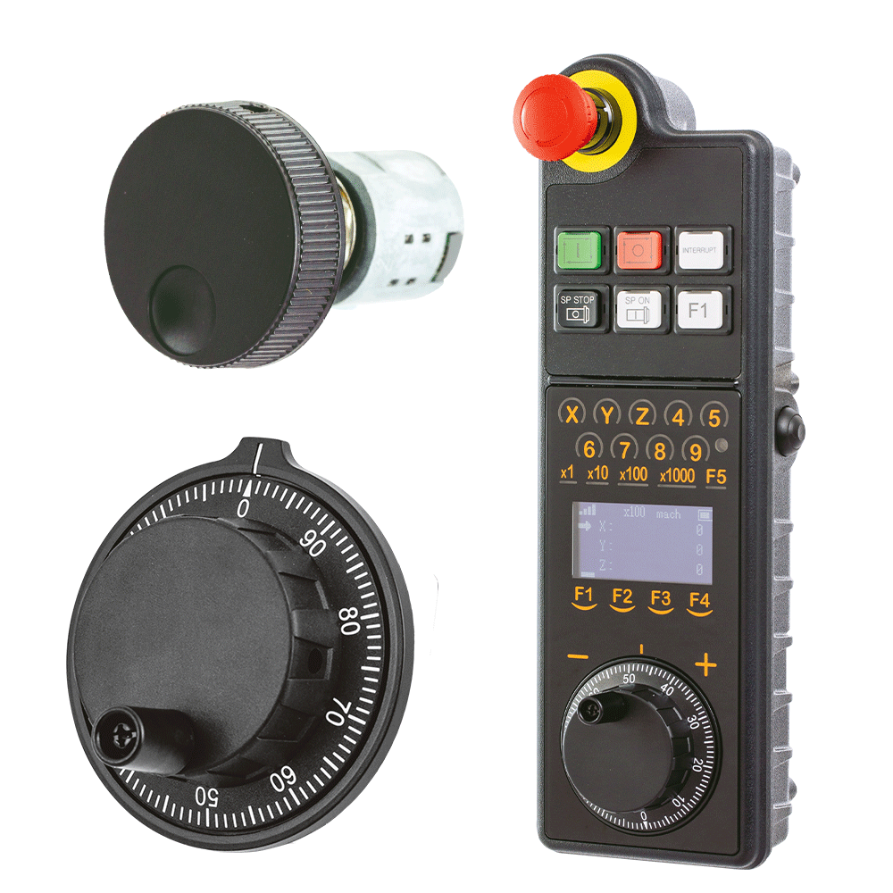
Gauging kit for HSK tool holder taper with pneumatic measuring column. The Multifunctional Measuring and Control Device is designed for high precision and multifunctional capabilities. In addition to providing various ways for measuring input, it can be customized to meet customer requirements.
Gauging kit for HSK tool holder taper with pneumatic measuring system.
Taper Air Jet RingHard chrome plated with 2 measuring levels according to ISO 12164-1 in accordance with Sketch Nr. 1392 with hose 1.5 meters long and quick connect coupler for connection to the MSG measuring column.
Taper Master PlugWith calibration step, according to ISO 12164-1 in accordance with Sketch Nr. 1401, hardened and aged steel with international certification.
L5 Clamping Shoulder – MechanicalFor the measurement of the L5 according to ISO 12164-1 in accordance with Sketch Nr. 1421 includes master and dial indicator.
Pre-measurement device for the tool holder flangeHSK tool shank according to ISO 12164-1 and Sketch 1477 including gauge with indicator and certificate.
Key GaugesMeasures the size and radius of HSK tool holder drive keys. Complete set with case includes measuring ring with dial indicator, measuring gauge for lower deviation, measuring gauge for upper deviation, mean deviation and setting gauge for dial indicator. The setting gauge is placed into the gauge ring, and the dial indicator is set to zero. The measuring gauge 1 is then used to measure the lower deviation of the drive key, and the measuring gauge 2 the upper deviation.
Multifunctional Measuring ColumnThe Multifunctional Measuring and Control Device is designed for high precision and multifunctional capabilities. In addition to providing various ways for measuring input, it can be customized to meet customer requirements. The Program Designer software is available to allow for additional measuring devices.
• Gauging and controls by in-process and post-process
• Pneumatic and tactile measurement
• Minimal air consumption, while holding high measuring stability
• Easy to operate
• Adaptable to statistical process control software
• Ability to network MLS and MSG columns together with output going to one location


")