|
|||
 |
|||
 |
|||
 |
|||
 |
|||
 |
|||
 |
||
 |
|||
 |
|||
 |
||
 |
|||
 |

Added functions helpful for detection
|
|
Functions helpful for production control
|
|
Ethernet supported
|
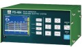
PS-482/484/488
PS-482/484/488


| Item | ||
| Detect | Channels | 2CH (PS-482) / 4CH (PS-484) / 8CH (PS-488) |
| Resolution | 1μm or 0.1μm | |
| Max. limit value | 200μm or 20.0μm | |
| Detect mode | Internal timing, External timing | |
| Max. SPM | 4000SPM | |
| Sensor | Sensor Installation distance (at B.D.C.) |
0.7 to 1.5 mm |
| Length of sensor cable | 1 to 10m (Standard 3m) | |
| Temperature | 0 to 55°C | |
| Input/Output | Power source voltage | 100 to 240 VAC ±10%,50/60Hz (Max. 40VA) |
| Relay output | EMG Stop, TDC Stop, READY,ALARM (Max. 250VAC / 30VDC 3.0A) |
|
| External input | ON/OFF, RESET, LOCK, TIMING (T1, T2, T3) | |
| Open collector output |
AUX (5 to 24 VDC 100mA) | |
| Ethernet | Physical layer | 10BASE-T/100BASE-TX |
| Protocol | IPv4 UDP、DHCP、HTTP、Telnet、FTP |
|
| Others | Dimensions of the body | 200(W)× 98.5(H)×190(D) excluding projections |
| Weight | 3.0 kgW (inc. mounting bracket) | |
| Temperature | 0 to 55°C (must not be sudden change while using it) | |
| Humidity | 35 to 85%RH (no dew condensation allowed) | |
| Click on image for more infomation. | ||||||
| PS-4013 | PS-4014 | PS-4018 | PS-4020 | PS-4024 | PS-4025 | PS-4026 |
| PS-4027 | PS-4028 | PS-4029 | PS-4031 | PS-4032 | PS-4033 | PS-4034 |
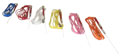
blue red white yellow Sensor Cable Series of 243297

High-sensitivity sensor with the resolution of 0.1μm
|
|
Visualization by a liquid crystal panel
|
|
Easy to adjust a detection timing
|
|
Data storage on a USB flash drive
|
|
Feature-rich settings
|
PS-474
PS-474

| Detection | |
| Number of channels | 4CH |
| Resolution | 1μm or 0.1μm |
| Max. limit value | 200μm or 20.0μm |
| Sensing distance of sensor head | 0.7 – 1.5nm |
| Ambient temperature of sensor head | 0 – 55°C |
| Type of timing | Internal timing , External timing |
| Length of sensor cable | Standard 3m |
| Max. SPM | 4000SPM |
| Record / Storage | |
| Number of record strokes (Approx.) | 60 million data |
| USB flash drive | Formatted USB flash drive with FAT32 in USB2.0 or less |
| External output | |
| Relay output | Max. 250VAC / 30VDC 3.0A |
| External input | |
| External Timing /Operation Lock / Reset / Monitor |
Connect non-voltage contact or semiconductor switch. Internal voltage (12 VDC) type |
| Power supply / Others | |
| Power source voltage | AC100V-240V ±10% 50/60Hz |
| Power consumption | peak:60W or less active:20W or less |
| Weight | 3.0kg(Only the main body) |
| Size of the body (WHD) | 200×200×190mm (excluding projections) |
| Ambient temperature | 0 – 55°C (must not be sudden change while using it) |
| Ambient humidity | 35 – 85%RH (no dew condensation allowed) |
| Ambient environmental | No corrosive gas or dust allowed |
| Attachments | Instruction manual 1 Proximity Sensor head 4 The sensor cable 4 Standard bracket 1 Output cable (Standard: 5 m) |
| Click on image for more infomation. | ||||||
| PS-4013 | PS-4014 | PS-4018 | PS-4020 | PS-4024 | PS-4025 | PS-4026 |
| PS-4027 | PS-4028 | PS-4029 | PS-4031 | PS-4032 | PS-4033 | PS-4034 |

Higher sensitivity
|
|
Displacement check with digital display and micron-indicator
|
|
Displayed gap for sensor installation
|
|
Flexible adjustment of the sensor cable length
|
|
Developed detection timing
|
|
Effective timing test
|
|
Detection of sensor wire disconnection
|
PS-462
PS-462

PS-464
PS-464


| Item | Specification | |
| Detection | The number of channels | 4 (PS-464) , 2 (PS-462) |
| Resolution | 1 μm or 0.1 μm | |
| Maximum setting value | 200 μm or 20.0 μm | |
| The closest gap between sensor head and target (BDC) | 0.7 ~ 1.5 mm | |
| Sensor Ambient operating temperature | 0 to 55 degree C | |
| Detection timing | External, internal, internal angle timing,and timer timing | |
| The length of sensor cable | 3 m (standard) | |
| SPM | 4000 SPM (max.) | |
| Output (Stop, Alarm, Continuous inhibition) | Relay output | 250 VAC / 30 VDC 3.0 A (max.) |
| External input (Reset, Monitor ON/OFF, Operation inhibition) | Input specification | Connect the contact of no-voltage or the semiconductor switch. Internal voltage (DC12 V) type |
| H level | 9.0V or over, 1mA or below | |
| L level | 3.0V or below, 8mA or over (12mA MAX) | |
| Display and setting | Micron-indicator | 61 Point Bar Graph |
| Displacement | Sign +3-digit | |
| ±Setting value | 3-digit | |
| Power source | Power supply voltage | AC100 ~ 240 V +/-10% 50/60Hz |
| Power consumption | 22 VA (max.) | |
| Weight | Body 2.8 kg (inc. mounting brackets.) | |
| Dimensions(WHD) | 200 * 98.5 * 184 mm (An umbo is not included.) | |
| Ambient operating temperature | 0 to 55 degree C (No sudden temperature change during the use.) | |
| Ambient operating humidity | 35~85% RH (non condensing) | |
| Attachments | Proximity Sensor head 2 (PS-462) , 4 (PS-464) The sensor cable 2 (PS-462) , 4 (PS-464) Output cable (Standard: 5 m) Instruction manual |
|
| Click on image for more infomation. | ||||||
| PS-4013 | PS-4014 | PS-4018 | PS-4020 | PS-4024 | PS-4025 | PS-4026 |
| PS-4027 | PS-4028 | PS-4029 | PS-4031 | PS-4032 | PS-4033 | PS-4034 |
blue red white yellow Sensor Cable Series of 243297 Order codes

| PS-4013 |  Click to enlarge image. PS-4013 |
 |
| PS-4014 |  Click to enlarge image. PS-4014 |
 |
| PS-4018 |  Click to enlarge image. PS-4018 |
 |
| PS-4020 |  Click to enlarge image. PS-4020 |
 |
| PS-4024 |  Click to enlarge image. PS-4024 |
 |
| PS-4025 |  Click to enlarge image. PS-4025 |
 |
| PS-4026 |  Click to enlarge image. PS-4026 |
 |
| PS-4027 |  Click to enlarge image. PS-4027 |
 |
| PS-4028 |  Click to enlarge image. PS-4028 |
 |
| PS-4029 |  Click to enlarge image. PS-4029 |
 |
| PS-4031 |  Click to enlarge image. PS-4031 |
 |
| PS-4032 |  Click to enlarge image. PS-4032 |
 |
| PS-4033 |  Click to enlarge image. PS-4033 |
 |
| PS-4034 |  Click to enlarge image. PS-4034 |
| PS-4013 | Click to enlarge image. PS-4013 |
|
| PS-4014 | Click to enlarge image. PS-4014 |
|
| PS-4018 | Click to enlarge image. PS-4018 |
|
| PS-4020 | Click to enlarge image. PS-4020 |
|
| PS-4024 | Click to enlarge image. PS-4024 |
|
| PS-4025 | Click to enlarge image. PS-4025 |
|
| PS-4026 | Click to enlarge image. PS-4026 |
|
| PS-4027 | Click to enlarge image. PS-4027 |
|
| PS-4028 | Click to enlarge image. PS-4028 |
|
| PS-4029 | Click to enlarge image. PS-4029 |
|
| PS-4031 | Click to enlarge image. PS-4031 |
|
| PS-4032 | Click to enlarge image. PS-4032 |
|
| PS-4033 | Click to enlarge image. PS-4033 |
|
| PS-4034 | Click to enlarge image. PS-4034 |
 |
| PS-4013 | Click to enlarge image. PS-4013 |
|
| PS-4014 | Click to enlarge image. PS-4014 |
|
| PS-4018 | Click to enlarge image. PS-4018 |
|
| PS-4020 | Click to enlarge image. PS-4020 |
|
| PS-4024 | Click to enlarge image. PS-4024 |
|
| PS-4025 | Click to enlarge image. PS-4025 |
|
| PS-4026 | Click to enlarge image. PS-4026 |
|
| PS-4027 | Click to enlarge image. PS-4027 |
|
| PS-4028 | Click to enlarge image. PS-4028 |
|
| PS-4029 | Click to enlarge image. PS-4029 |
|
| PS-4031 | Click to enlarge image. PS-4031 |
|
| PS-4032 | Click to enlarge image. PS-4032 |
|
| PS-4033 | Click to enlarge image. PS-4033 |
|
| PS-4034 | Click to enlarge image. PS-4034 |
|

Improvement of operability by LCD
|
|
Provided with helpful functions for production control
|
|
Ethernet supported
|
|
Enhancement of sensor feature
|
PS-682
PS-682


| Item | Specifications | |
| Detect | Channels | 6 Channels |
| Detect mode | Touch, Synchronization, Passage, Feed, Extraction, Timer, Counting feed |
|
| Power source for sensors (by the total) |
12VDC (Max. 500mA) 24VDC (Max. 200mA) |
|
| Output response time | Max. 10 ms | |
| Counter | Digits | Total Counter:6 Preset Counter:6 |
| Output response time | Max. 10ms | |
| Input/output | Power source voltage | 100 to 240 VAC ±10%, 50/60Hz (Max. 40 VA) |
| Relay output | EMG Stop, TDC Stop, READY, ALARM (Max. 250 VAC / 30 VAC 3.0A) |
|
| External input | ON/OFF, RESET, LOCK,TIMING (T1, T2, T3) | |
| Sensor input | No-voltage contact 3-wire NPN open collector |
|
| Ethernet | Physical layer | 10BASE-T/100BASE-TX |
| Protocol | IPv4 DHCP, HTTP, TELNET | |
| Others | Temperature | 0 to 55°C (must not be sudden change while using it) |
| Humidity | 35 to 85%RH (no dew condensation allowed) | |
| Dimensions of the body | 200(W) × 120(H) × 190(D) excluding projections | |
| Weight | 3.4 kgW (inc. mounting bracket) | |
| DINP-1J(White)(Pin – DIN conversion cable) | |
 |
 Click to enlarge image. DINP-1J |
| DINP-3J(Black)(3-pole plug – DIN conversion cable) | |
 |
 Click to enlarge image. DINP-3J |
| Click on image for more information. | ||
| Light sensor (OS series) | Light sensor (LS series) | |
 |
 |
|
| Loop sensor | Spring sensor | |
 |
 |
|
| Acoustic sensor | ||
 |
||

The detection modes can be changed.
|
|
| The sensor input polarity of each channel can be switched. | |
All detection channels have the pin jack and the 3-contact jack.
|
|
The detection channel under use is displayed.
|
|
The operation stop of the safety device is made easy to confirm.
|
|
Large-scale figure LED is built in the counter display.
|
|
Unnecessary operation can be excluded.
|
PS-661
PS-661

PS-662
PS-662

| Specification | Detection channels | 6 |
| Detection timings | 3 input | |
| Power source for sensor | 12 V , 600 mA (max.) | |
| Detection style | 6 types (Touch, Synchronization, Extraction, Timer, Passage, Miss-feed) | |
| SPM | 1500 SPM (max.) | |
| Output | Emergency, T.D.C., alarm, continuous inhibition | |
| Relay output | 250 VAC / 30 VDC , 2A (max.) | |
| Input | Input Specification | Internal volt system (12 VDC) |
| H level | 9.0V or over, 1mA or below | |
| L level | 3.0V or below, 8mA or over (12mA MAX) | |
| Counter (PS-662) |
Digits | 6 |
| Count speed | 1500 SPM (max.) | |
| Backup | 2 weeks | |
| Power source | Power supply voltage | AC100 ~ 240 V +/-10% 50/60Hz |
| Power consumption | 20 VA (max) | |
| Weight | Body 2.4 kg (PS-661), Body 2.5 kg (PS-662) (inc. mounting brackets.) | |
| Dimensions(WHD) | 200 * 98.5 * 184 mm (PS-661) 200 * 118.5 * 184 mm (PS-662) (An umbo is not included.) |
|
| Ambient operating temperature | 0 to 55 degree C (No sudden temperature change during the use.) | |
| Ambient operating humidity | 35~85% RH (non condensing) | |
| Attachments | Output cable (Standard: 5 m) US-1 5 (blue, white, yellow, orange, pink) US-2 1 (red) Instruction manual |

| The timing signal from the press, both the limit switch and the adjacent switch are also possible. | |
| Two functions are installed in the Passage detection unit. | |
| The timing signal circuit is equipped with the timing timer function. |
PS-101T
PS-101T

| Detection channels | 1 |
| Detection mode | Passage (modes1,2) |
| Voltage of detection circuit | DC12 V |
| Timing mode | Timer timing (25 ms ~ 2.5 s) |
| Voltage of timing circuit | DC12 V |
| Stop output circuit | Relay output AC200 V 2 A (max.) |
| Stop output delay time | Approx. 25 ms |
| Power supply voltage | AC100 V ~ 200 V |
| Ambient operating temperature | 0 to 55 degree C (No sudden temperature change during the use.) |
| Dimensions(WHD) | 170 * 49 * 146 mm (An umbo is not included.) |
| Weight | Body 1.9 kg (inc. mounting brackets.) |
| Power consumption | Approx. 7 VA |
| Attachments | Output cable (Standard: 5 m) US-1 1(red) Instruction manual |

| With the toggle switch, the input polarity of all channels is immediately switchable to A or B. | |
| If the timing signal is input, CH1 turns to the synchronous detection method. | |
| The power supply of an electronic sensor can be provided from the 3-contact jack to CH1. | |
| Remote resetting is available by connecting the external reset. | |
| Turning off the power supply switch of PS-104F can prohibit the press machine from continuously operating if the continuous inhibition output is connected. | |
| The stop outputs are two systems (CH1/2 and CH3/4). |
PS-104F
PS-104F

PS-104F

| Detection channels | 4 |
| Detection mode | Detect the touch or break (The rotation and the synchronization of the press can be taken in CH1. ) |
| Stop output circuit | Relay output AC200 V 2 A (max.) |
| Stop output delay time | Approx. 5 mS |
| Power supply voltage | AC100 ~ 200 V |
| Ambient operating temperature | 0 to 55 degree C (No sudden temperature change during the use.) |
| Dimensions(WHD) | 200 * 68.5 * 184 mm (An umbo is not included.) |
| Weight | Body 2.0 kg (inc. mounting brackets.) |
| Consumption | Approx. 7 VA (max.) |
| Attachments | Output cable (Standard: 5 m) US-1 4(red,blue,yellow,orange) Instruction manual |

| USE Series Order codes | USD Series USE Series |
US series Leaflet USD series Leaflet USE series Leaflet |
| US-1 | |
 |
 Click to enlarge image. US-1 |
| US-2 | |
 |
 Click to enlarge image. US-2 |
| US-3 | |
 |
 Click to enlarge image. US-3 |
| US-4 | |
 |
 Information on material change and price revision of spring sensor US-4 Click to enlarge image. US-4 |
| US-5 | |
 |
 Click to enlarge image. US-5 |
| US-7S | |
 |
 Click to enlarge image. US-7S |
| US-7L | |
 |
 Click to enlarge image. US-7L |
| USD-1 | |
 |
 Click to enlarge image. USD-1 |
| USD-2 | |
 |
 Click to enlarge image. USD-2 |
| USD-3 | |
 |
 Click to enlarge image. USD-3 |
| USD-4 | |
 |
 Information on material change and price revision of spring sensor USD-4 Click to enlarge image. USD-4 |
| USD-5 | |
 |
 Click to enlarge image. USD-5 |
| US-7S | |
|
Click to enlarge image. US-7S |
| USD-7L | |
 |
 Click to enlarge image. USD-7L |
| USE-1 *Production on orders | |
 |
 Click to enlarge image. USE-1 Order codes |
| USE-2*Production on orders | |
 |
 Click to enlarge image. USE-2 Order codes |
| USE-E *Production on orders | |
 |
 Click to enlarge image. USE-E Order codes |
| USE-DE*Production on orders | |
 |
 Click to enlarge image. USE-DE Order codes |