
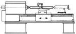
Lathe runout test bars are used to verify alignment between centers as well as main and sub spindles for A2 and flat nose.

Arbors for Centers
A2 Spindle Arbors

Flat-Nose Arbors
Workholding Collet Arbors

Lathe Face Arbor Cases
VDI

Turret With Pilot
Turret Without Pilot

Turret Right Angle

Lathe Spindle Face Ring
Lathe Spindle Face Ring With Indicator Mounts

Taper Plug Gauges Without Flange
Taper Plug Gauges With Flange
Taper Plug Gauges With Indicator Mounts

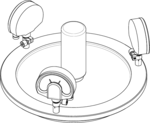
The Lathe Bridge Alignment Gauge provides an easy-to-use reference surface for an A2 lathe spindle interface.

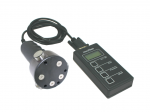
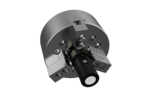
Turning-center force sensors are designed to measure the holding force of clamp jaws on chucks. This allows manufacturers to make critical adjustments, and improve repeatability and workpiece quality. The wireless version of the chuck force gauge is able to measure RPM along with force.
The ForceCheck wireless chuck force gauge is designed to quickly and accurately measure holding force and speed on chucks. Verifying chuck holding force allows manufacturers to improve the repeatability of a manufacturing process by checking actual holding force under dynamic (rotating) conditions, as well as perform critical preventative maintenance checks. Contact us for other clamping diameters and extension rings, as well as 4+ jaw chucks.
| Item | Jaws | Diameter | Force Range (per Jaw) | Part Number | ||||
|---|---|---|---|---|---|---|---|---|
| D28 | 2 / 3 | 28 mm / 1.10 in. | 0…15kN / 3,400 lb-F | 495.205.028.003 | ||||
| D72 | 2 / 3 | 72 mm / 2.83 in. | 0…50kN / 11,200 lb-F | 495.205.072.003 | ||||
| D72 | 4 | 72 mm / 2.83 in. | 0…50kN / 11,200 lb-F | 495.205.072.004 | ||||
| D125 | 2 / 3 / 4 | 125 mm / 4.92 in. | 0…65kN / 14,600 lb-F | 495.205.125.004 | ||||
| D200 | 2 / 3 / 4 / 6 | 200 mm / 7.87 in. | 0…100kN / 22,500 lb-F | 495.205.200.006 | ||||
| D28 (Low Force) | 2 / 3 | 28 mm / 1.10 in. | Contact us | 495.205.028.003.LF | ||||
| D72 (Low Force) | 2 / 3 | 72 mm / 2.83 in. | Contact us | 495.205.072.003.LF | ||||
| D125 (Low Force) | 2 / 3 / 4 | 125 mm / 4.92 in. | Contact us | 495.205.125.004.LF | ||||
| D200 (Low Force) | 2 / 3 / 4 / 6 | 200 mm / 7.87 in. | Contact us | 495.205.200.006.LF |
Designed to quickly check the holding force on a chuck or turning-center. The wired chuck force gauge can be customized for any diameter.
| Measuring Diameter | Jaws | Diameter | Force Range (per Jaw) | Part Number | ||||
|---|---|---|---|---|---|---|---|---|
| D28 | 2 / 3 | 28 mm / 1.10 in. | 0…15kN / 3,400 lb-F | 495.200.028.003 | ||||
| D72 | 2 / 3 | 72 mm / 2.83 in. | 0…50kN / 11,200 lb-F | 495.200.072.003 | ||||
| D125 | 2 / 3 / 4 | 125 mm / 4.92 in. | 0…65kN / 14,600 lb-F | 495.200.125.004 | ||||
| D200 | 2 / 3 / 4 / 6 | 200 mm / 7.87 in. | 0…100kN / 22,500 lb-F | 495.200.200.006 | ||||
| D28 (Low Force) | 2 / 3 | 28 mm / 1.10 in. | Contact us | 495.200.028.003.LF | ||||
| D72 (Low Force) | 2 / 3 | 72 mm / 2.83 in. | Contact us | 495.200.072.003.LF | ||||
| D125 (Low Force) | 2 / 3 / 4 | 125 mm / 4.92 in. | Contact us | 495.200.125.004.LF | ||||
| D200 (Low Force) | 2 / 3 / 4 / 6 | 200 mm / 7.87 in. | Contact us | 495.200.200.006.LF |

")
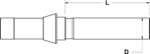
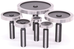
TAC Rockford runout arbors for lathe centers are manufactured using hardened gauge-quality steel, and include a certificate of accuracy.
| Description | Length (L) | Diameter (D) | Part Number | |||||
|---|---|---|---|---|---|---|---|---|
| Runout Arbor for Centers | 250 mm | 32 mm | 490.520.032.250 | |||||
| Runout Arbor for Centers | 300 mm | 32 mm | 490.520.032.300 | |||||
| Runout Arbor for Centers | 400 mm | 35 mm | 490.520.035.400 | |||||
| Runout Arbor for Centers | 500 mm | 40 mm | 490.520.040.500 | |||||
| Runout Arbor for Centers | 600 mm | 50 mm | 490.520.050.600 | |||||
| Runout Arbor for Centers, Special | Contact Us | Contact Us | 490.520.SP |

")
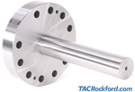
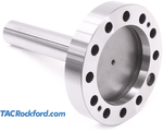
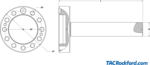
A2-8 Lathe Runout Test Bar
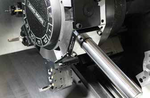
Test arbor for mounting to turning-center and measuring run-out. Designed for A2-5, A2-6, D1-8 etc. lathe face mounting. Also available for flat 110 and 140 lathe face.
Extended drawbar clearance versions have additional depth at the taper needed for drawbar clearance on certain lathes.
| Lathe Face | Length (L) | Dia. (D) | Standards | Part Number | ||||
|---|---|---|---|---|---|---|---|---|
| A2-3 | Contact us | ISO702-1 / DIN55026 / JIS B 6109-1 / ASME B5.9 |
490.610.A2-3 | |||||
| A2-4 | Contact us | ISO702-1 / DIN55026 / JIS B 6109-1 / ASME B5.9 |
490.610.A2-4 | |||||
| A2-5 | 300 mm | 50 mm | ISO702-1 / DIN55026 / JIS B 6109-1 / ASME B5.9 |
490.610.A2-5 | ||||
| A2-6 | 300 mm | 50 mm | ISO702-1 / DIN55026 / JIS B 6109-1 / ASME B5.9 |
490.610.A2-6 | ||||
| A2-8 | 300 mm | 50 mm | ISO702-1 / DIN55026 / JIS B 6109-1 / ASME B5.9 |
490.610.A2-8 | ||||
| A2-11 | 300 mm | 50 mm | ISO702-1 / DIN55026 / JIS B 6109-1 / ASME B5.9 |
490.610.A2-11 | ||||
| A2-15 | 300 mm | 50 mm | ISO702-1 / DIN55026 / JIS B 6109-1 / ASME B5.9 |
490.610.A2-15 | ||||
| A2-20 | 300 mm | 50 mm | ISO702-1 / DIN55026 / JIS B 6109-1 / ASME B5.9 |
490.610.A2-20 | ||||
| A2-4 Extended Drawbar Clearance | 300 mm | 50 mm | ISO702-1 / DIN55026 / JIS B 6109-1 / ASME B5.9 |
490.610.A2-4.001 | ||||
| A2-4 Willemin Macodel | 150 | 40 | Special version for Willemin Macodel 408MT / 508MT2 |
490.610.A2-4.84236 | ||||
| A2-5 Extended Drawbar Clearance | 300 mm | 50 mm | ISO702-1 / DIN55026 / JIS B 6109-1 / ASME B5.9 |
490.610.A2-5.001 | ||||
| A2-6 Extended Drawbar Clearance | 300 mm | 50 mm | ISO702-1 / DIN55026 / JIS B 6109-1 / ASME B5.9 |
490.610.A2-6.001 | ||||
| A2-8 Extended Drawbar Clearance | 300 mm | 50 mm | ISO702-1 / DIN55026 / JIS B 6109-1 / ASME B5.9 |
490.610.A2-8.001 | ||||
| D1-8 | 300 mm | 50 mm | ASME B5.9 | 490.610.D1-8 | ||||
| Custom Configuriation | Contact us | 490.610.SP |
| Lathe Face | Length (mm) | Diameter (mm) | Standard | Part Number | ||||
|---|---|---|---|---|---|---|---|---|
| Flat 110 | 300 | 50 | ISO 702-4 / JIS B 6109-2 | 490.610.F110 | ||||
| Flat 140 / ISM 52 | 300 | 50 | ISO 702-4 / JIS B 6109-2 | 490.610.F140 | ||||
| Flat 220 / ISM 102 | 300 | 50 | ISO 702-4 / JIS B 6109-2 | 490.610.F220 | ||||
| Flat 380 | 300 | 50 | ISO 702-4 / JIS B 6109-2 | 490.610.F380 | ||||
| Index D65 | 300 | 40 | For Index Werke C65, G160, A200, C200 Machines | 490.610.94327 |

")
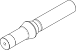
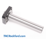
TF Swiss Collet Runout Test Arbor
TAC Rockford workholding spindle runout test bars provide a definitive standard for verifying the accuracy of 5C, TF, BS, and other collet spindles.
Designed for precision collet chucks, Swiss-style lathes, indexing heads, and grinding fixtures, a runout test bar provides an immediate, reliable baseline to diagnose spindle health, troubleshoot vibration issues, and certify machine alignment.
Additional product information can be found on the Details tab below.
| Swiss Collet Type / Size | Length (L) | Diameter (D) | Part Number | |||||
|---|---|---|---|---|---|---|---|---|
| 5C | 200 mm | 32 mm | 487.05C.000.000 | |||||
| TF10 | 70 mm | 10 mm | 487.TF10.000.000 | |||||
| TF15 | 70 mm | 15 mm | 487.TF15.000.000 | |||||
| TF16 | 70 mm | 15 mm | 487.TF16.000.000 | |||||
| TF20 | 100 mm | 21 mm | 487.TF20.000.000 | |||||
| TF25 | 100 mm | 25 mm | 487.TF25.000.000 | |||||
| TF30 | 100 mm | 32 mm | 487.TF30.000.000 | |||||
| TF43 | 100 mm | 46 mm | 487.TF43.000.000 | |||||
| TF48 | 100 mm | 50 mm | 487.TF48.000.000 | |||||
| BS20 | 100 mm | 27 mm | 487.BS20.000.000 | |||||
| BS38 | 100 mm | 42 mm | 487.BS38.000.000 | |||||
| Other size or special configuration | Contact Us | 487.WHC.SP |


Lathe turret alignment bar for VDI interface. Used for both testing concentricity of the interface as well as center alignment and adjustment on a lathe. Made to DIN 69880 standard. 465.V50.59767 is a special configuration used on certain Mazak machines. Contact us for further information. Contact us for other sizes or special requirements/configurations.
| DIN 69880 | L | D1 | D2 | D3 | Standards | Part Number | ||
|---|---|---|---|---|---|---|---|---|
| VDI 16 | 120 | 30 | 16 | 40 | DIN 69880 | 465.V16.000.000 | ||
| VDI 20 | 150 | 40 | 20 | 50 | DIN 69880 | 465.V20.000.000 | ||
| VDI 25 | 150 | 40 | 25 | 58 | DIN 69880 | 465.V25.000.000 | ||
| VDI 30 | Contact Us | 30 | DIN 69880 | 465.V30.000.000 | ||||
| VDI 40 | 200 | 40 | 40 | 83 | DIN 69880 | 465.V40.000.000 | ||
| VDI 50 | 200 | 40 | 50 | 98 | DIN 69880 | 465.V50.000.000 | ||
| VDI 50 Mazak | 200 | 40 | 50 | 92 | Special for Mazak | 465.V50.59767 | ||
| VDI 60 | 200 | 40 | 60 | 123 | DIN 69880 | 465.V60.000.000 | ||
| VDI Special Configuration | Custom order | 465.V00.SP |

")
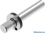
TL-40Y Lathe Turret Alignment Bar
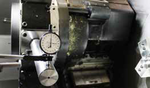
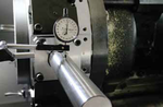
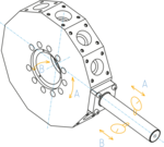
Lathe turret test bars provide an easy way to verify turret perpendicularity. Bars are installed in the turret like a standard tool. Test bars have an accuracy of 0.003mm (0.00012 inch) and include a certificate. Optional carrying cases available.
| Machine | L | D1 | D2 | A1/A2 | B1/B2 | D | Interface/Models | Part Number |
|---|---|---|---|---|---|---|---|---|
| DMG Mori | 220 | 40 | 40 | 31/31 | 35/35 | 11 | CTX310ECO-BMT / NZ1500 / NZ2000 | 490.137.00193 |
| DMG Mori | 300 | 60 | 50 | 42/42 | 47/47 | 13 | NLX1500-NLX2000 / NLX2500-NLX3000 NL2000 (S)MC-2500 (S)MC / NL3000MC (12 Stations) |
490.137.00194 |
| Okuma | 300 | 60 | 50 | 36.5/36.5 | 26/39 | 14 | LB2000 EX (M, MY) / LB2500 EX (M) LB3000 EX (M, MY) / LB3000 EX (MW, MYW) |
490.137.00195 |
| Okuma | 300 | 60 |
50 | 39/39 | 40/40 | 13 | LB4000 EX (M, MY) | 490.137.00196 |
| Doosan | 220 | 45 | 40 | 29/29 | 29/29 | 9 | BMT45 • LYNX 220LM | 490.137.00197 |
| Doosan | 220 | 45 | 40 | 29/29 | 29/29 | 9 | BMT55 • PUMA230-240M / MS-280LM-1500-2000-2500M/MS/S/SY 2100 SERIES-TT1500-TT1800MS/SY / TL2000-2500LM-MX1600/2100TS LYNX 300M |
490.137.00198 |
| Doosan | 300 | 65 | 50 | 36.5/36.5 | 35/35 | 13 | BMT65 • PUMA300M/MS-V400M-TT2000SY-TT2500SY TT2500MS-2600/3100 Series / MX2000ST-MX2500T/ST/LST-VT450/TM Inverturn 3000M |
490.137.00199 |
| Doosan | 300 | 75 | 50 | 45/45 | 45/45 | 13 | BMT75 • PUMA400-480M/LM/XLM-VT 750M/TM | 490.137.00200 |
| Mazak | 225 | 68 | 40 | 34/34 | 45/65 | 9 | QTS200M | 490.137.00201 |
| Mazak | 300 | 65 | 50 | 36/36 | 60/85 | 11 | QTS300M | 490.137.00202 |
| Biglia | 220 | 55 | 40 | 31.5/31.5 | 32.5/32.5 | 11 | B301/445/470/501(Y-S)/510/545/550/565/650/658 1200/446/465/745/765-B750/1250 16 ST BV210/315 |
490.137.00209 |
| DMG Mori | 300 | 59.94 | 50 | 32.6/32.6 | 40.2/35.1 | 14 | TL-40Y/4000 | 490.137.00283 |
| 300 | 60 | 50 | 42/42 | 47/47 | 13 | 490.137.79807 | ||
| 300 | 55 | 50 | 25/25 | 30/30 | 11 | 490.137.86338 | ||
| 200 | 55 | 50 | 25/25 | 30/30 | 12 | 490.137.86338.1 | ||
| 215 | 68 | 40 | 34/34 | 45/65 | 8.5 | 490.137.87223 | ||
| 200 | 44 | 40 | 20/20 | 27.5/27.5 | 8.5 | 490.137.88752 |
Lathe turret test bars provide an easy way to verify turret perpendicularity. Bars are installed in the turret like a standard tool. Test bars have an accuracy of 0.003mm (0.00012 inch) and include a certificate. Optional carrying cases available.
| Part Number | ||||||||
|---|---|---|---|---|---|---|---|---|
| 300 | N/A | 50 | 38/38 | 35/35 | 13 | 490.137.89442 |
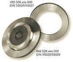
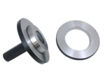
Series 492.026 ring gauges are for lathe spindle face. Ring only: order plug gauge separately (see series 492.028 or 492.228)
| Standards | Size | d2 max. | d2 min. | Gauge | Part Number | |||
|---|---|---|---|---|---|---|---|---|
| DIN55026-3, DIN55027-3, A1-3, A2-3, B1-3, B2-3 | 3 | 53.983 | 53.975 | Ring | 492.026.003.000 | |||
| DIN55026-4, DIN55027-4, A1-4, A2-4, B1-4, B2-4 | 4 | 63.521 | 63.513 | Ring | 492.026.004.000 | |||
| DIN55026-5, DIN55027-5, A1-5, A2-5, B1-5, B2-5 | 5 | 82.573 | 82.563 | Ring | 492.026.005.000 | |||
| DIN55026-6, DIN55027-6, A1-6, A2-6, B1-6, B2-6 | 6 | 106.385 | 106.375 | Ring | 492.026.006.000 | |||
| DIN55026-8, DIN55027-8, A1-8, A2-8, B1-8, B2-8 | 8 | 139.731 | 139.719 | Ring | 492.026.008.000 | |||
| DIN55026-11, DIN55027-11, A1-11, A2-11, B1-11, B2-11 | 11 | 196.883 | 196.869 | Ring | 492.026.011.000 |
Series 492.126 ring gauges are for lathe spindle face.
| Lathe Spindle Face Ring | Part Number | |||||||
|---|---|---|---|---|---|---|---|---|
| A2-3 | 492.126.003.000 | |||||||
| A2-4 | 492.126.004.000 | |||||||
| A2-5 | 492.126.005.000 | |||||||
| A2-6 | 492.126.006.000 | |||||||
| A2-8 | 492.126.008.000 | |||||||
| A2-11 | 492.126.011.000 | |||||||
| A2-15 | 492.126.015.000 |
Taper gauges can be custom-manufactured to customer specifications. Hard chrome-plate and tungsten carbide gauges also available. Cases are not included. Contact us for high quality gauge crib and travel case options.
| Chuck Taper Plug Gauge | Standards | Part Number | ||||||
|---|---|---|---|---|---|---|---|---|
| A2-3 | ISO702-1 / DIN55026 / JIS B 6109-1 / ASME B5.9 | 492.228.003.000 | ||||||
| A2-4 | ISO702-1 / DIN55026 / JIS B 6109-1 / ASME B5.9 | 492.228.004.000 | ||||||
| A2-5 | ISO702-1 / DIN55026 / JIS B 6109-1 / ASME B5.9 | 492.228.005.000 | ||||||
| A2-6 | ISO702-1 / DIN55026 / JIS B 6109-1 / ASME B5.9 | 492.228.006.000 | ||||||
| A2-8 | ISO702-1 / DIN55026 / JIS B 6109-1 / ASME B5.9 | 492.228.008.000 | ||||||
| A2-11 | ISO702-1 / DIN55026 / JIS B 6109-1 / ASME B5.9 | 492.228.011.000 | ||||||
| A2-15 | ISO702-1 / DIN55026 / JIS B 6109-1 / ASME B5.9 | 492.228.015.000 |
Taper gauges can be custom-manufactured to customer specifications. Hard chrome-plate and tungsten carbide gauges also available. Cases are not included. Contact us for high quality gauge crib and travel case options.
| Taper Size | Standards | Part Number | ||||||
|---|---|---|---|---|---|---|---|---|
| A2-3 | ISO702-1 / DIN55026 / JIS B 6109-1 / ASME B5.9 | 492.028.003.000 | ||||||
| A2-4 | ISO702-1 / DIN55026 / JIS B 6109-1 / ASME B5.9 | 492.028.004.000 | ||||||
| A2-5 | ISO702-1 / DIN55026 / JIS B 6109-1 / ASME B5.9 | 492.028.005.000 | ||||||
| A2-6 | ISO702-1 / DIN55026 / JIS B 6109-1 / ASME B5.9 | 492.028.006.000 | ||||||
| A2-8 | ISO702-1 / DIN55026 / JIS B 6109-1 / ASME B5.9 | 492.028.008.000 | ||||||
| A2-11 | ISO702-1 / DIN55026 / JIS B 6109-1 / ASME B5.9 | 492.028.011.000 |


")
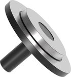
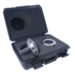
A2 Taper Gauge with Dial Indicators
Taper gauges can be custom-manufactured to customer specifications. Hard chrome-plate and tungsten carbide gauges also available. Indicators and carrying case are not included. Contact us for high quality gauge crib and travel case options.
| Taper Plug Gauge w/ Indicator Mounts | Standards | Part Number | ||||||
|---|---|---|---|---|---|---|---|---|
| A2-3 | ISO702-1 / DIN55026 / JIS B 6109-1 / ASME B5.9 | 492.128.003.000 | ||||||
| A2-4 | ISO702-1 / DIN55026 / JIS B 6109-1 / ASME B5.9 | 492.128.004.000 | ||||||
| A2-5 | ISO702-1 / DIN55026 / JIS B 6109-1 / ASME B5.9 | 492.128.005.000 | ||||||
| A2-6 | ISO702-1 / DIN55026 / JIS B 6109-1 / ASME B5.9 | 492.128.006.000 | ||||||
| A2-8 | ISO702-1 / DIN55026 / JIS B 6109-1 / ASME B5.9 | 492.128.008.000 | ||||||
| A2-11 | ISO702-1 / DIN55026 / JIS B 6109-1 / ASME B5.9 | 492.128.011.000 | ||||||
| A2-15 | ISO702-1 / DIN55026 / JIS B 6109-1 / ASME B5.9 | 492.128.015.000 |


")
")
")
")